
Receiver Box
Table of Contents
Overview
The 14m receiver box contains 3 receivers, for 2.2 GHz, 4.8 GHz, and 6.7 GHz. These are all mounted on a sliding platform, so that each of the 3 receivers can be positioned at the focus of the dish.
Things which are not on the sliding platform:
- Some connectors going outside the box
- A motor to drive the platform (a re-purposed drill).
- A motor drive board (a PCB with some relays on it).
- Limit/position switches so that we know which receiver is in position.
Things on the sliding platform:
- Some RF hardware (horn antennas, amplifiers, mixers etc).
- 4 FET servos. These are controllers to control the current through and voltage across the low noise RF amplifiers. Only for the 4.8 and 6.7 GHz receivers.
- A PCB with a PIC microcontroller. This selects which receiver is to be used by controlling the platform motor, and RF relays. The whole receiver box is controlled through this PIC via RS232.
PIC board
This is a custom PCB with a PICAXE 40X1 microcontroller, and a bunch of other glue logic. The PICAXE could be replaced with a 40X2 with only minor changes to the code. The git repository for the PICAXE code has a branch labelled 'master_40X2' with these changes.
The entire receiver box is controlled through this PIC board via RS232. It has the following functionality:
- Accepts commands over RS-232
- Determines the platform's current position from the switches.
- Controls the motor to move the platform.
- Controls the RF relays to enable a specific receiver.
- Measures various voltages, and sends them out over RS-232:
- low-noise amplifier FET voltages/currents,
- local oscillator lock status,
- temperature,
- receiver box supply voltage.
PIC Board Commands
These are the commands that the PIC accepts over RS-232 (at 2400 baud). Each command is a single byte lowercase letter. The commands to move in to a position could take 10 seconds or more to complete.
'Print' means the PIC will send it over RS-232.
| Byte to send | Command | What it does |
| 2 | 2.2 GHz | Moves the 2.2 GHz receiver into position |
| 4 | 4.8 GHz | Moves the 4.8 GHz receiver into position |
| 6 | 6.7 GHz | Moves the 6.7 GHz receiver into position |
| d | dump | Sends the measurements from the ADC in binary |
| l | long status | Prints a long status line (human readable) |
| s | short status | Prints a short status (single byte ASCII character) |
| v | version | Print version string |
The long and short status lines that the PIC can send are:
| Short | Long | Description |
| "M" | "Multiple switches are pressed. Position unknown." | If multiple switches are pressed down (for whatever reason) the PIC cannot determine the position of the platform |
| "2" | "2.2Ghz in position." | |
| "4" | "4.8Ghz in position." | |
| "6" | "6.7Ghz in position." | |
| "U" | "In unknown position." | No position switches are pressed. |
States "M" and "U" should never happen.
Interfacing with the ADC
The output from a 'dump' command is 35 bytes, corresponding to the 35 ADC channels which it can measure. There is a QBasic program on Eric's computer in "My Documents\14m_analogue_interpreter\" which shows what each ADC channel does. Also see the PIC Board Headers section.
PIC Board Hardware Details
Voltage regulation
The PIC board has two separate 5V regulators: one to power the 5V relays, and one to provide a stable supply for all the digital components on the board.
Relays
The relays on the PIC board are:
- 8 DPDT relays which the PIC can control directly, labelled 8, 16, 24, 32, 40, 48, 56, 64. For each relay, one pole switches 24V and the other pole switches 5V. This is because some of the RF relays require 24V and some require 5V.
- a black remnant relay, which is controlled by two of the other relays, (40) and (56).
- a DPDT relay controlled by the remnant relay, used to make a 'direction reverser' for the grey relay. This is required because the remnant relay is not DPDT.
The PIC uses 4 output pins (bits 3, 4, 5, 6 of PORTB) to control the relays. These 4 pins connect directly to a 4-to-16 line decoder, so that one of the 8 relays can be turned on at any given time. Eight of the outputs of the line decoder are connected to an 8-way transistor array, which can sink enough current to actually power the relays. (Only 8 of the outputs of the line decoder are used, so there is only one 8-way transistor array.) Due to the way the line decoder and relays are wired, if you write the value 56 to PORTB, then the relay (56) will turn on, etc... Setting PORTB=0 will turn off all relays.
| Relay number | Wire and voltage |
| (8) | G [5V] |
| (16) | H [5V] |
| (24) | C [24V] |
| (32) | E [5V] |
| (40) | S [5V], P [24V] |
| (48) | F [5V] |
| (56) | J [5V], P [24V] |
| (64) | In series with the 24V supply going to the grey relay. This will set either T or V to 24V depending on the state of the remnant relay |
In order to switch the grey relay, you must first activate either (40) or (56) to set the remnant relay, then pulse (64).
35 ADC Channels
The PIC board can measure 35 different analogue voltages, but the PIC only has 7 analogue inputs. The PIC analogue inputs A0, A1, A2, A3 are each connected to a 8-way analogue switches, giving a total of 32 analogue inputs. The PIC analogue inputs A5, A6, A7 just measure one thing each, for a total of 35.
The 8-way analogue switches have 3 control lines (2^3 = 8), which are connected to the PIC PORTB pins 0,1,2. Thus, to read one of the 32 analogue inputs, first write a value 0-7 to PORTB, then read one of A0, A1, A2, A3.
MAX232 Dual Purpose
The PIC board has a MAX232 chip, which converts RS-232 voltage levels to TTL and vice-versa. This is used for a second purpose, in addition to its intended one. The MAX232 has a charge pump circuit to generate +-7.5V for the RS-232. On this PIC board, those voltages are also used to power an op amp. (This op amp converts the -20V supply voltage of the receiver box to a voltage that the PIC's ADC can measure.)
Circuit and printing
The board was designed in DipTrace, and the file is located on Eric's computer at "My Documents\14m_pic_schematic\". There are a few bodge wires on the physical board, but the DipTrace designs have been updated to make it equivalent to the physical board with its bodge wires.
Headers
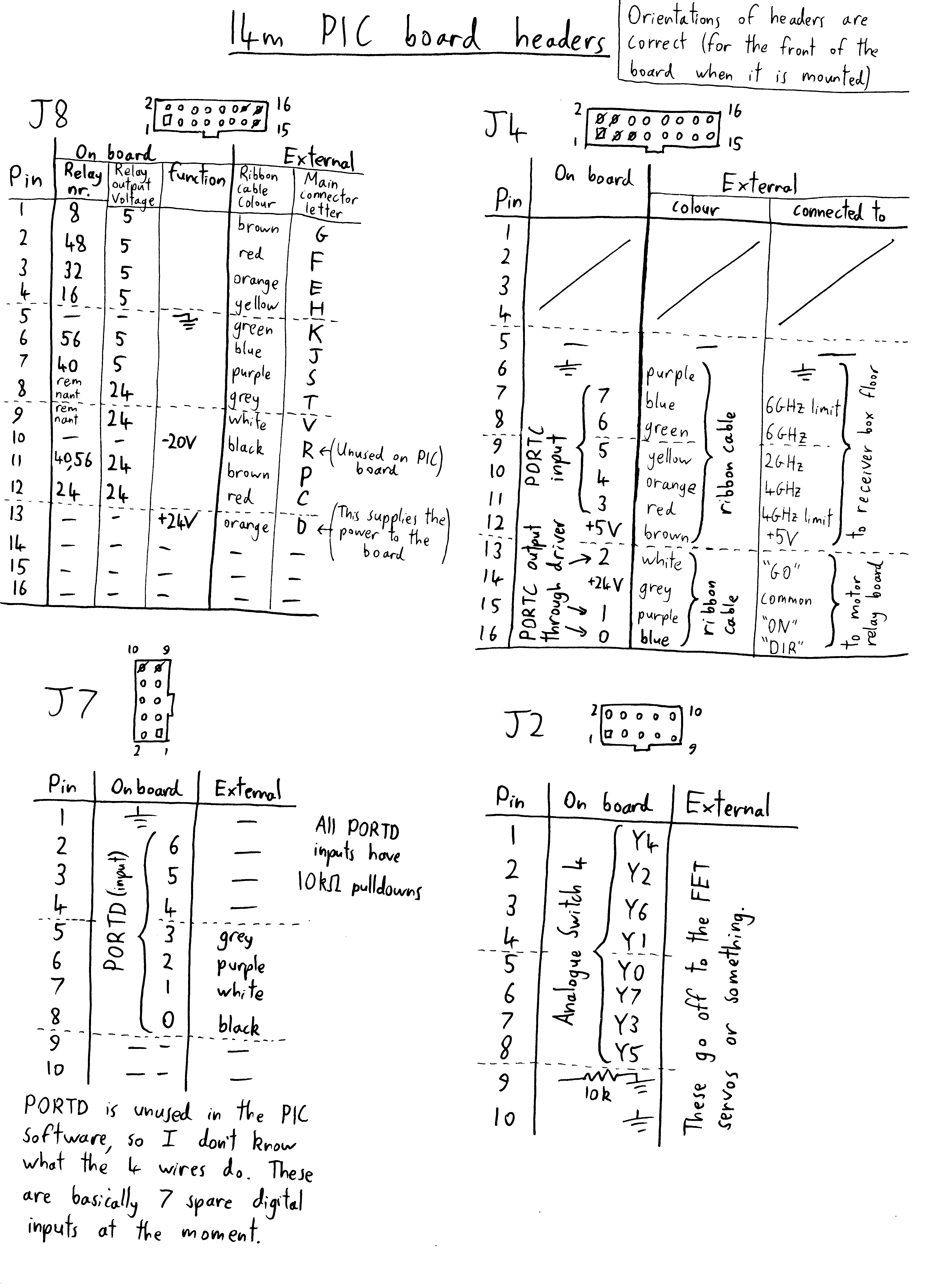
PIC board IDC pinouts.
The PIC board has 5 IDC connectors. Going from top-to-bottom, then left-to-right:
- J8: 20-pin (13 are used). Goes directly to the 'main' connector of the receiver box. Also goes to the RF relays.
- J4: 20-pin (11 are used). Goes to the motor position switches, and motor relay board.
- J7: 10-pin (4 are used). Goes to somewhere unknown (not used in the PIC code).
- J1: 40-pin. Inputs to the ADCs of the PIC. Measures FET servo voltages/currents.
- J2: 10-pin. Inputs to ADCs. Measures miscellaneous things.
40-pin and 10-pin ADC Headers
These two headers (at the bottom of the PCB) connect various voltages (on the RF hardware) to the ADCs of the PIC, so they can be measured.
Each FET servos |FET servo board contains 3 FET servos, and each servo has 2 measurements:
- D: Drain voltage
- C: Current
For instance 'D2' refers to the drain voltage of the second servo.
| Connections on Board | External Connections | ||||||
| Header Pin # | connection | Analogue switch # | Analogue switch input | Wire colour | PSU | FET servo board | FET measurement |
| 1 | 1 | 1 | brown | 4 | D1 | ||
| 2 | 1 | 2 | red | 4 | C1 | ||
| 3 | - | orange | +20V | ||||
| 4 | 1 | 0 | yellow | 4 | D2 | ||
| 5 | GND | green | GND | ||||
| 6 | op amp ADC | blue | -20V | ||||
| 7 | 1 | 3 | purple | 4 | C2 | ||
| 8 | - | grey | - | ||||
| 9 | 1 | 4 | white | 4 | D3 | ||
| 10 | GND | black | GND | ||||
| 11 | 1 | 6 | brown | 4 | C3 | ||
| 12 | 1 | 7 | red | 3 | D1 | ||
| 13 | - | orange | - | ||||
| 14 | 1 | 5 | yellow | 3 | C1 | ||
| 15 | GND | green | GND | ||||
| 16 | - | blue | - | ||||
| 17 | 2 | 2 | purple | 3 | D2 | ||
| 18 | 2 | 1 | grey | 3 | C2 | ||
| 19 | 2 | 0 | white | 3 | D3 | ||
| 20 | GND | black | GND | ||||
| 21 | 2 | 3 | brown | 3 | C3 | ||
| 22 | 2 | 4 | red | 2 | D1 | ||
| 23 | - | orange | - | ||||
| 24 | 2 | 6 | yellow | 2 | C1 | ||
| 25 | GND | green | GND | ||||
| 26 | - | blue | - | ||||
| 27 | 2 | 7 | purple | 2 | D2 | ||
| 28 | 2 | 5 | grey | 2 | C2 | ||
| 29 | 3 | 2 | white | 1 | D1 | ||
| 30 | GND | black | GND | ||||
| 31 | 3 | 1 | brown | 1 | C1 | ||
| 32 | 3 | 0 | red | 1 | D2 | ||
| 33 | - | orange | - | ||||
| 34 | 3 | 3 | yellow | 1 | C2 | ||
| 35 | 3 | 4 | green | 1 | D3 | ||
| 36 | - | blue | - | ||||
| 37 | 3 | 6 | purple | 2 | D3 | ||
| 38 | 3 | 7 | grey | 2 | C3 | ||
| 39 | 3 | 5 | white | 1 | C3 | ||
| 40 | GND | black | GND | ||||
The following table contains the same data as the table above, but rearranged in order of FET servo board. The 4 FET servo board also have a colour (yellow, green, red, blue) which is the colour of the heat shrink on the cables going from the servo to the LNA.
| FET servo board | On PIC Board | ||||
| colour | # | measurement | Analogue switch # | Analogue switch input | Header Pin # |
| yellow | 1 | D1 | 3 | 2 | 29 |
| 1 | C1 | 3 | 1 | 31 | |
| 1 | D2 | 3 | 0 | 32 | |
| 1 | C2 | 3 | 3 | 34 | |
| 1 | D3 | 3 | 4 | 35 | |
| 1 | C3 | 3 | 5 | 39 | |
| green | 2 | D1 | 2 | 4 | 22 |
| 2 | C1 | 2 | 6 | 24 | |
| 2 | D2 | 2 | 7 | 27 | |
| 2 | C2 | 2 | 5 | 28 | |
| 2 | D3 | 3 | 6 | 37 | |
| 2 | C3 | 3 | 7 | 38 | |
| red | 3 | D1 | 1 | 7 | 12 |
| 3 | C1 | 1 | 5 | 14 | |
| 3 | D2 | 2 | 2 | 17 | |
| 3 | C2 | 2 | 1 | 18 | |
| 3 | D3 | 2 | 0 | 19 | |
| 3 | C3 | 2 | 3 | 21 | |
| blue | 4 | D1 | 1 | 1 | 1 |
| 4 | C1 | 1 | 2 | 2 | |
| 4 | D2 | 1 | 0 | 4 | |
| 4 | C2 | 1 | 3 | 7 | |
| 4 | D3 | 1 | 4 | 9 | |
| 4 | C3 | 1 | 6 | 11 | |
| Connections on Board | External Connections | |||
| Header Pin # | Analogue switch # | Analogue switch input | Wire colour | Description |
| 1 | 0 | 4 | brown | Beige connector 2, white wire near the purple end. Board A, left NARDA relay, white wire. Tells us if the 4GHz 'H' relay is on. |
| 2 | 0 | 2 | red | Beige connector 2, grey wire near the red end. Board A, 12V regulator output |
| 3 | 0 | 6 | orange | Beige connector 2, red wire near the purple end. Board A, 24V rail |
| 4 | 0 | 1 | yellow | Beige connector 1, brown wire near the purple end. Board B, some regulator. |
| 5 | 0 | 0 | green | Black connector that goes to the LO board, orange wire. LO board yellow wire, 6GHz lock. |
| 6 | 0 | 7 | blue | Black connector that goes to the LO board, yellow wire. LO board yellow wire, 2.65GHz lock. |
| 7 | 0 | 3 | purple | Beige connector 1, black wire near the purple end. Board B, right NARDA relay. Tells us if the 4GHz 'H' relay is on |
| 8 | 0 | 5 | grey | Beige connector 1, orange wire. Board B thermometer |
| 9 | - | - | white | - |
| 10 | - | - | black | - |
PIC code
The PIC is programmed using PICAXE basic. The code with comments is on Eric's computer, at "My Documents\14m_drive_program\". If you want more details, read the code and its comments.
There are a few other branches in the git repository:
- master_40X2 has modifications so the code will run on a PICAXE 40X2
- relay_testing allows you to specify exactly with motor relays are on or off (by writing a value 0-7 to RS-232)
- rf_relay_testing is similar, but for the RF relays
Platform position state machine
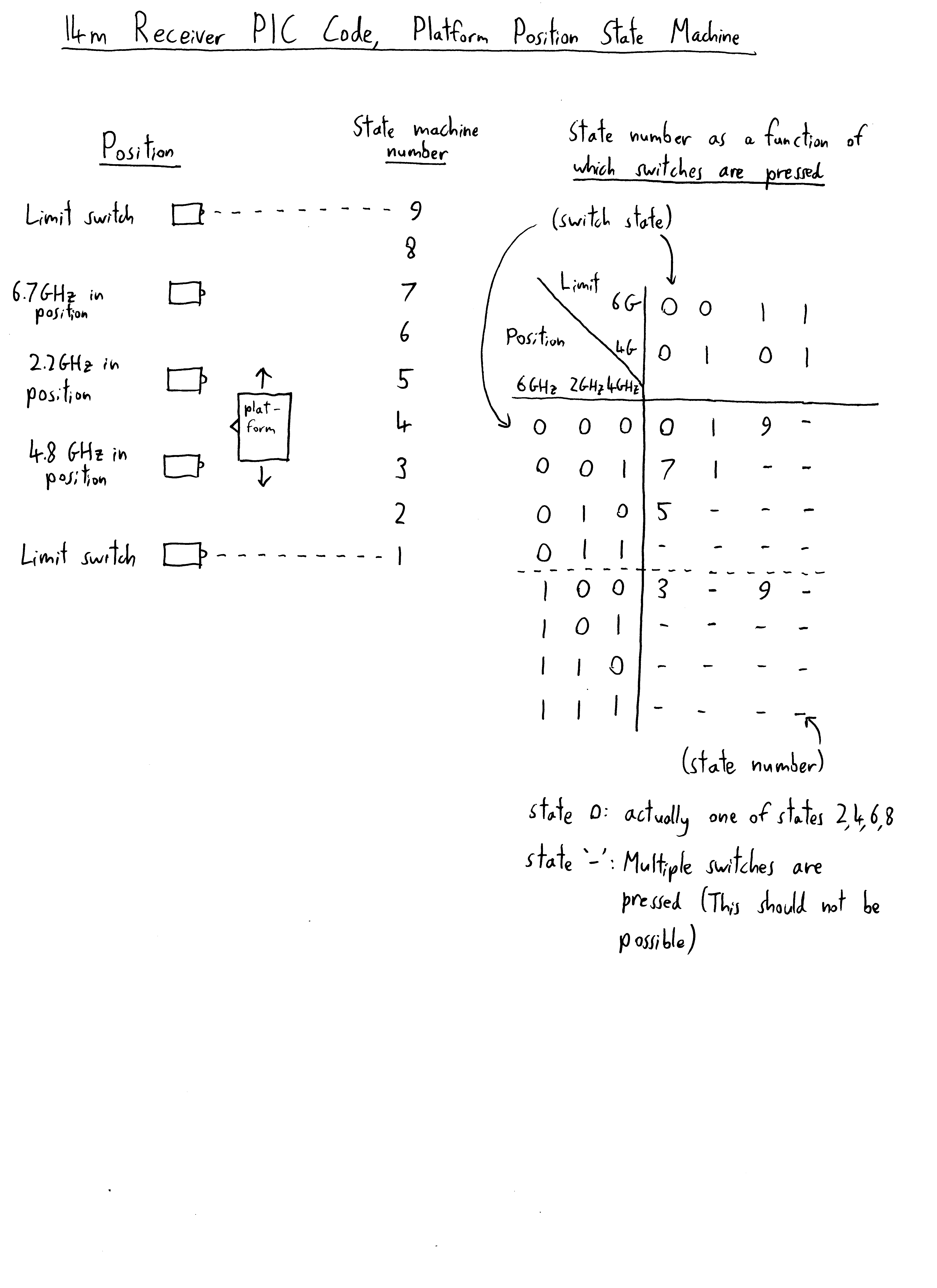
PIC code platform position state machine.
The PIC program must be able to determine the position of the platform, but is only able to measure the state of the 5 position switches. In order to keep track of the platforms position, it implements a state machine, with possible state numbers:
- 1-9: as shown in the figure to the right. Values 1, 3, 5, 7, and 9 are when a single switch is pressed. Values 2, 4, 6 and 8 are when the platform is between switches.
- 0: position unknown. If the PIC boots in between switches, it cannot tell which state out of 2, 4, 6 or 8 it is in.
- 255: multiple switches are pressed. This is in case the PIC thinks that more than one switch is pressed (should only occur if there is a hardware error). The PIC will not try to move the platform.
There is an exception to the 'multiple switches pressed' rule. It is physically possible for both the 4 GHz position switch and limit switches to be pressed. In this case it is treated as if the platform is in the 4 GHz limit (not 4 GHz in position). This is why there are two '1's in the state table to the right. Similarly for the 6 GHz end (there are two '9's in the table to the right).
All this may seem a overly complicated, however it makes the system robust.
It also confines all the complicated code to the PICAXE BASIC function 'getPosition', leaving the functions 'putPlatformInPosition', 'motorForwards', 'motorReverse' relatively straightforward.
PICAXE pinout
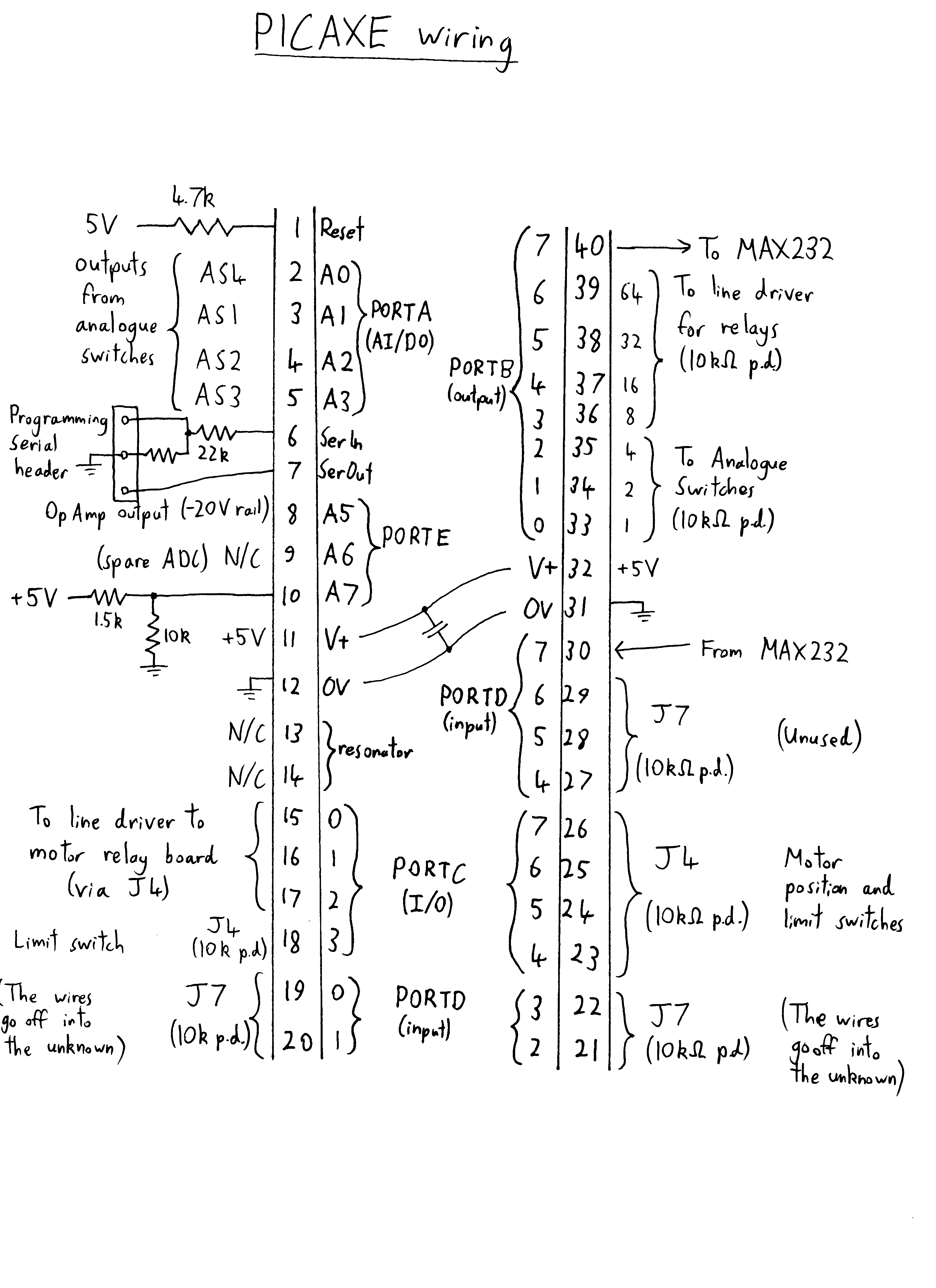
PIC chip pinout
In the figure to the right, J4 and J7 are IDC headers on the PIC board, and AS1, AS2, AS3, AS4 are the analogue switches.
RF hardware
The receiver has 3 RF 'boards' (which are aluminium plates to which some RF components are attached):
- A local oscillator board,
- Two RF-to-IF mixer boards, for the two polarisations.
In order to select a receiver, some RF relays must be set to:
- Route the signal from the chosen receiver to a mixer.
- Select the correct local oscillator frequency and give it to the mixer.
RF local oscillator board
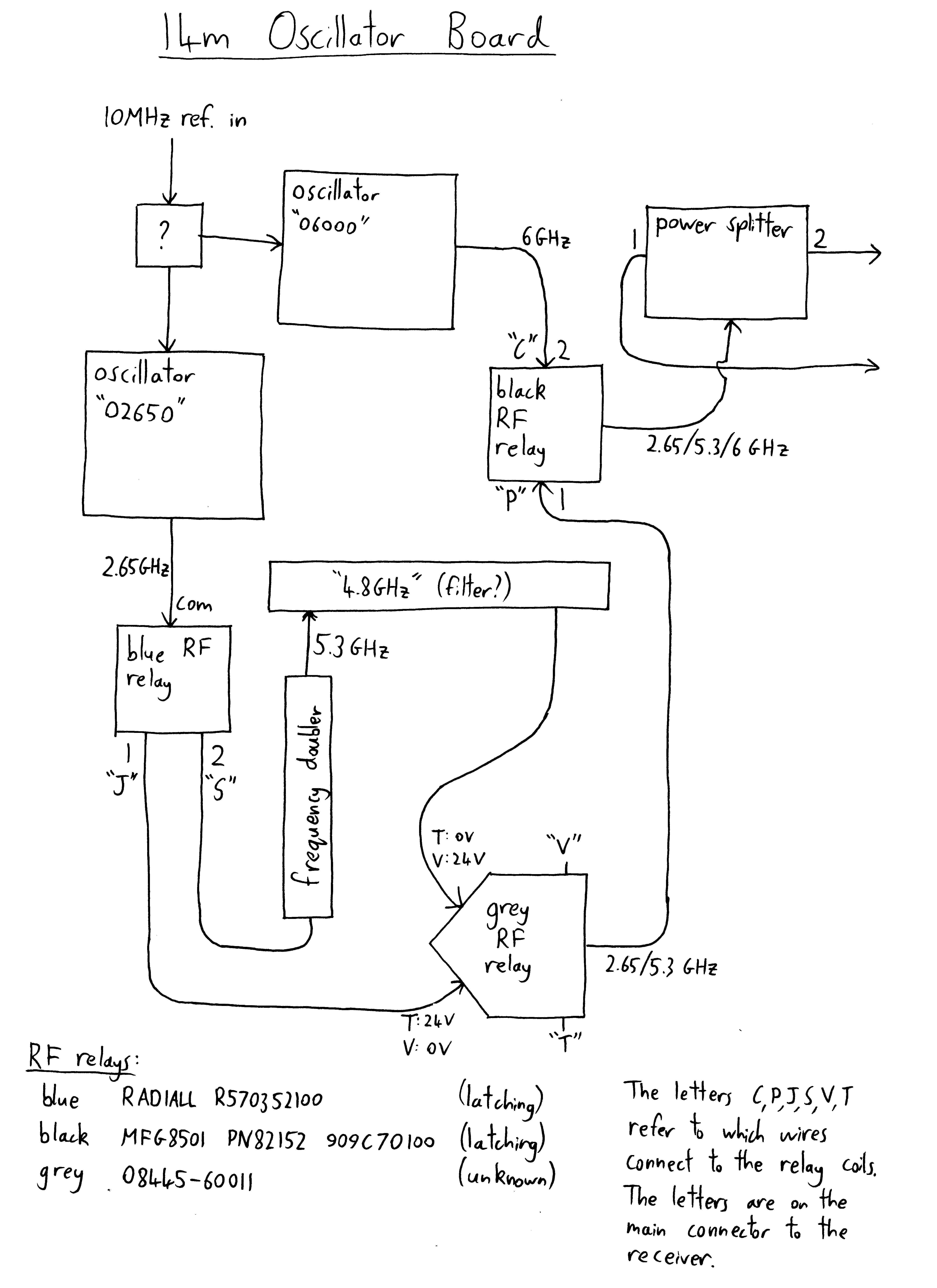
Local oscillator RF board
This generates a signal to be mixed with the RF to produce the IF. It produces two identical outputs, which go to the two RF-IF mixer boards.
Input: 10 MHz reference.
Output: 2.65, 5.3 or 6 GHz.
There are only two oscillators: a 6 GHz one and a 2.65 GHz one. For 2.65 and 6 GHz output, the relays just switch in the respective oscillator. For 5.3 GHz output, the output from the 2.65 GHz oscillator is fed into a frequency doubler, and then into a filter (which is presumably a 5.3 GHz band-pass filter).
The letters (C, P, J, S, T, V) in the figure to the right refer to the pins of the 'main connector'.
Also note the grey relay connected to T and V, which is a bit tricky to drive.
RF filter and mixer boards
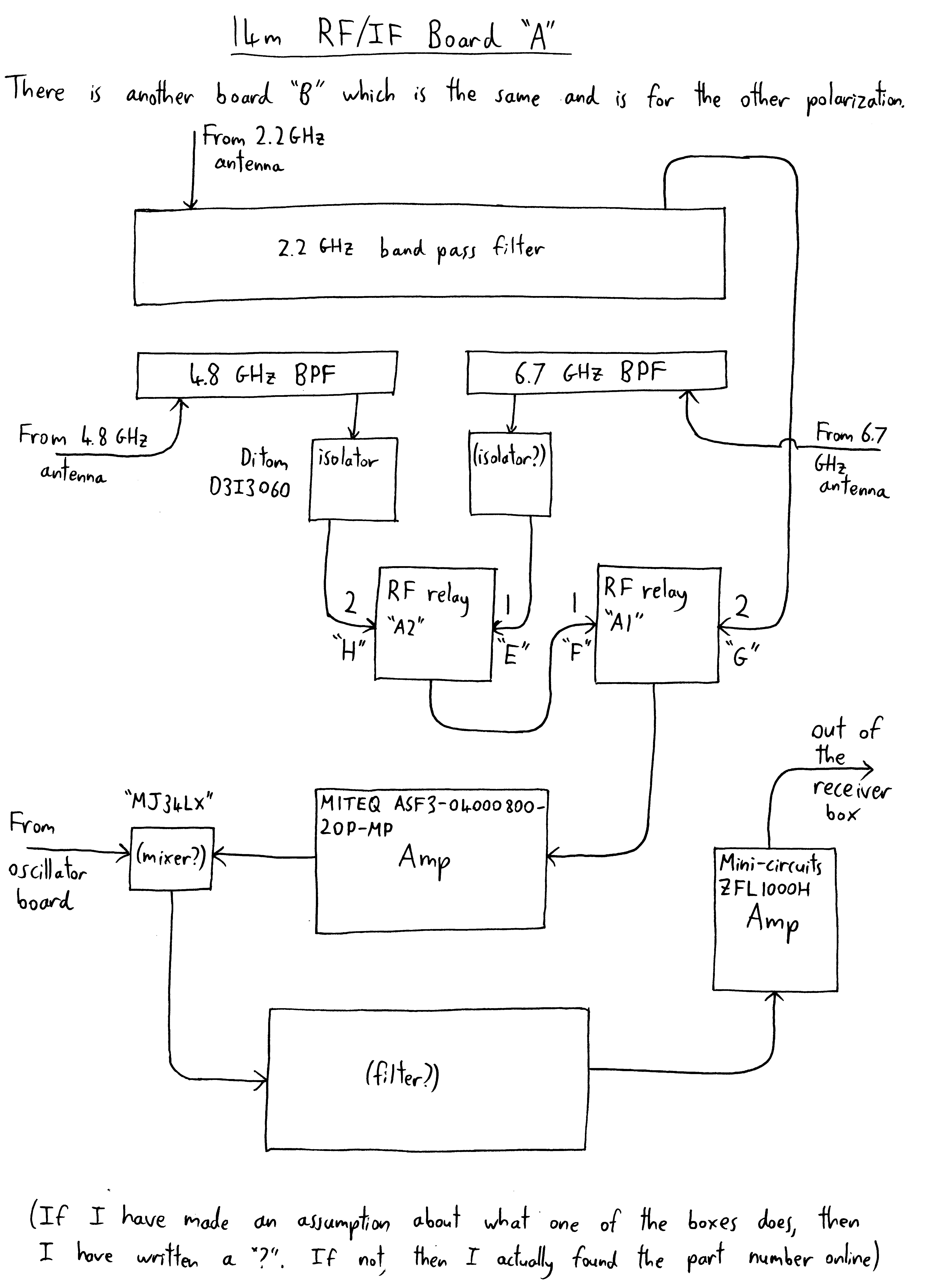
RF to IF filter and mixer board
There are two of these boards, one for each polarization.
For each receiver, and each polarization, the signal from the sky goes through:
- A horn antenna.
- A low noise amplifier (which I think is basically just a transistor with some biasing). For the 4.8 and 6.7 GHz, these are biased using a FET servo.
- A band-pass filter.
- (optional) an RF isolator.
The amplified sky frequency signal from each antenna then goes through some RF relays, which choose one of the 3 receivers. Then, the chosen signal goes through:
- Another amplifier.
- A mixer (mixes the sky frequency with the local oscillator).
- Another amplifier.
- Out of the receiver box through some coax.
The letters (G, F, E, H) in the figure to the right refer to the pins of the 'main connector'.
RF relays
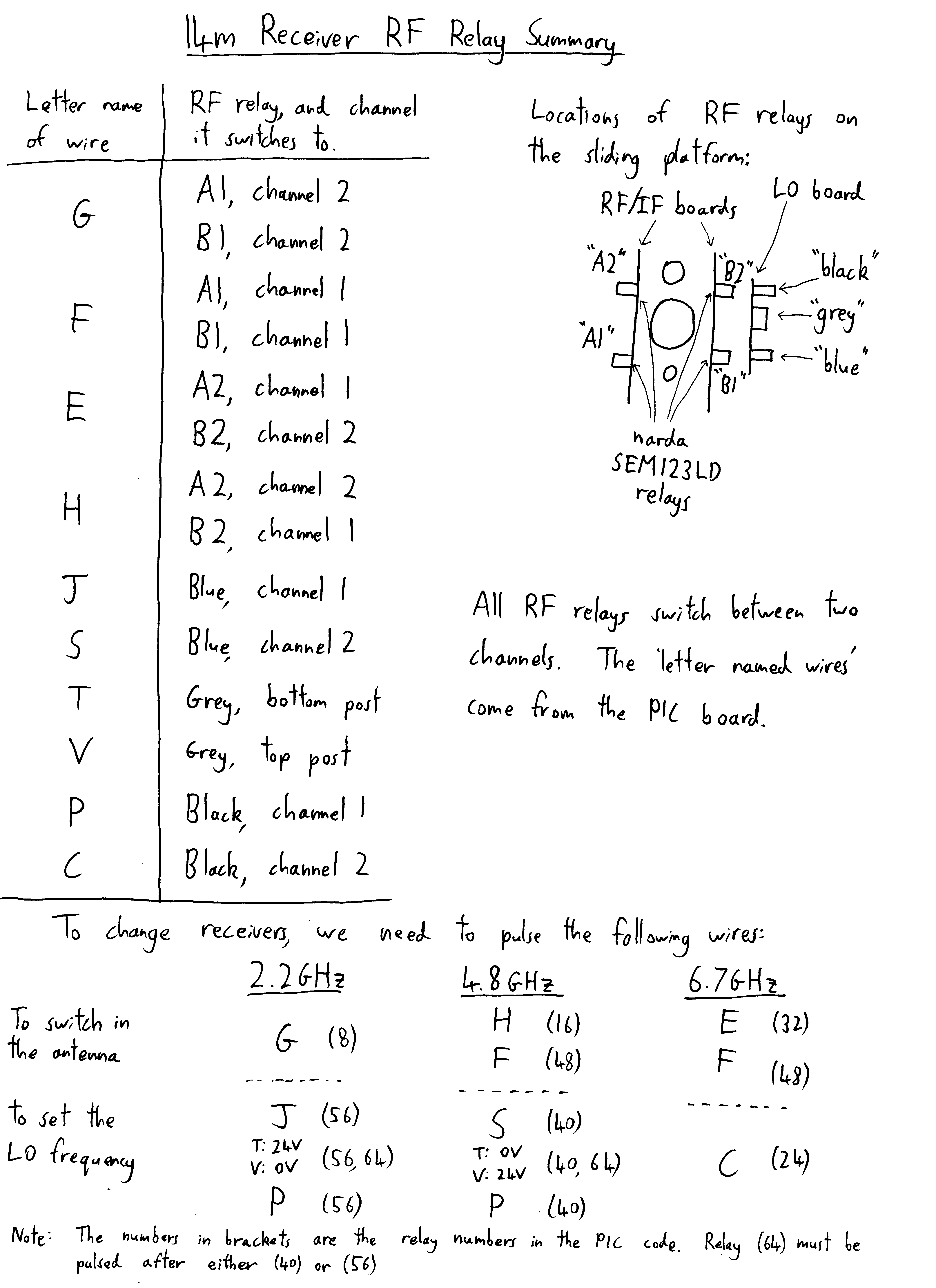
RF relay position settings
All of the RF relays are latching.
All the RF relays (with the exception of the grey one) just require a pulse of either 5V or 24V on the correct pin. The 5V relays actually contain some control circuitry, and they can accept a TTL signal.
In the figure to the right, the relays are named A1, A2, B1, B2 are on the RF-IF boards A and B, and select one receiver to use. These two boards are (practically) identical, and operate in parallel, so there are only 4 control lines (G, F, E, H) to these 4 relays.
The relays 'blue', 'grey' and 'black' are on the local oscillator board, and select the LO frequency. The 6 control lines (J, S, T, V, C, P) control these 3 relays.
These letters refer to the pins of the main connector.
The figure to the right shows which control lines (and which relays) must be activated in order to select a given receiver.
The grey RF relay
This relay has only two control pins (T and V), and requires a polarised voltage across them.
To change to channel '1', ground pin T, and apply +24V to pin V.
To change to channel '2', ground pin V, and apply +24V to pin T.
Note that you have to specifically ground one of the pins (it is not connected to ground internally).
This mean you need to use a DPDT relay, wired in a sort of h-bridge, as shown in the figure here, like the 'DIR' motor direction relay.
Manual receiver selector
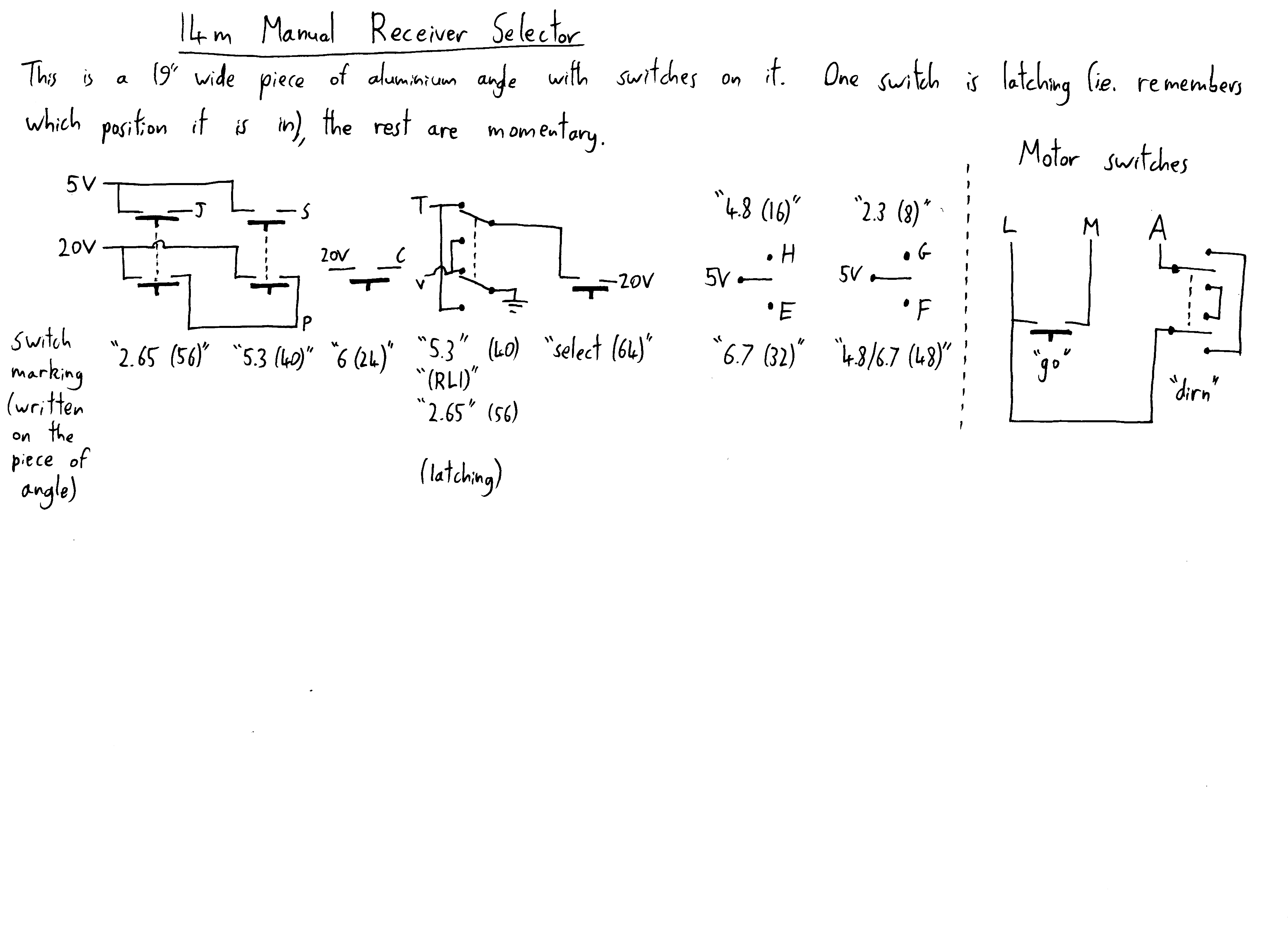
The old panel to manually control the RF relays and platform motor
Originally, the RF relays and platform drive motor were controlled manually. In the cabinet below the telescope there was a 19" wide piece of aluminium angle with some switches on it. The switches were wired directly to the RF relays via the 'main connector'.
The figure to the right shows the switches of this panel, and how they were wired. The letters (G, F, E, H, J, P, S, T, V) refer to the pins of the main connector. The only tricky thing is the relays connected to the letters T and V, which go to the grey RF relay.
This manual selector panel has been replaced by the PIC board, and each switch on this panel has been replaced by a relay.
The parenthesised numbers (8, 16, 24, 32, 40, 48, 56, 64) in the figure to the right refer to the number which must be written to PORTB in the PIC code, in order to switch on the respective relay.
FET servos
There are 3 receivers, each with 2 polarisations, so there are a total of 6 low-noise amplifiers. The 2.2 GHz receiver has 2 off-the-shelf LNAs, which just take +15V.
For the 4.8 and 6.7 GHz receivers there are a total of 4 (custom made, I think) 3-stage FET amplifiers. The quiescent current and voltage of each FET is controlled by a servo circuit, and they have all been tuned for minimum noise. There are 4 FET servo boards, each with 3 independent servos for the 4 3-stage LNAs.
The voltage and current for each of the 12 FETs can be measured by the PIC.
Connectors to receiver box
The connectors which go out the the box are:
- The 'Main connector', 19 pins.
- One DE-9 connector for RS-232, which goes to the PIC.
- Some RF connectors:
- N-type(?): 10 MHz reference input (red cable)
- N-type(?): Polarization 'A' output (blue cable)
- N-type(?): Polarization 'B' output (blue cable)
- N-type(?): Unknown (green cable)
- BNC: Unknown (yellow cable)
- BNC: Unused
'Main' connector
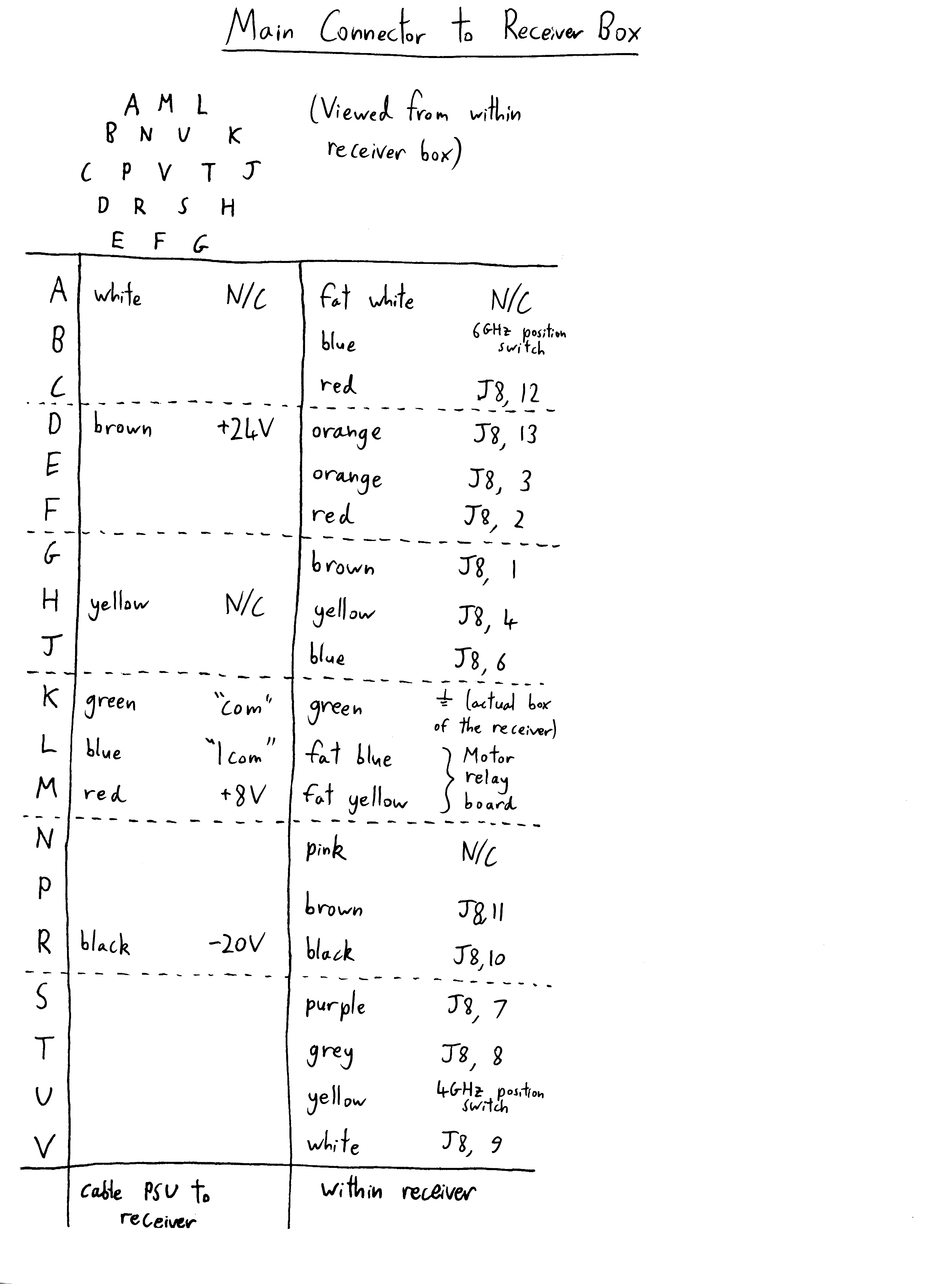
'Main' connector pinout. 'J8' refers to the header on the PIC board
This is a 19-pin connector, which was once served several purposes. However, now only 5 of the pins are being used, which provide DC power to the box.
The other pins connect (inside the box) to the RF relays, so it could be used to control the RF relays manually, without using the PIC.
Before the creation of the PIC board, the RF relays were controlled (via this connector) by a control panel covered in switches.
Platform motors
There is a sliding platform which holds the 3 receivers (2.2, 4.8 and 6.7 GHz), and allows any one of the receivers to be placed at the focus of the dish. This platform does not have full 'xyz' control of position, in fact it does not even have 'x' control. Instead, the platform has a little tooth which can press one of three switches to indicate that a receiver is in position. Additionally, there are 2 limit switches.
Motor drive relay board
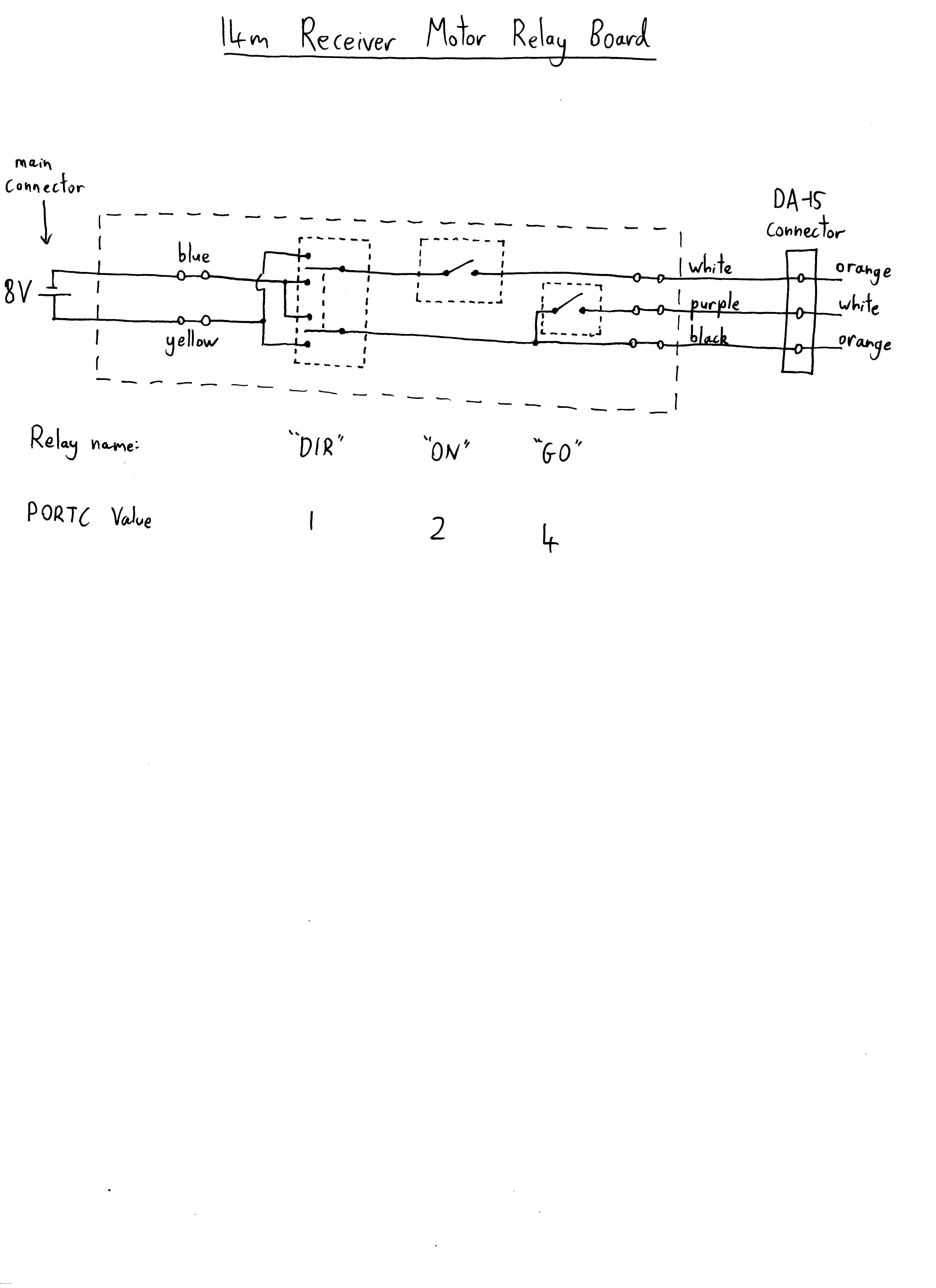
Motor relay PCB.
There are 3 relays, which are controlled by 3 pins of PORTC on the PIC:
- PORTC=1 'DIR': reverses the motor direction.
- PORTC=2 'ON': Turns the motor on (but can be over-ridden by the position switches).
- PORTC=4 'GO': Forces the motor to turn on (can be over-ridden by the limit switches, but not the position switches).
The switches can be controlled independently.
Example: say the platform is on a position switch, and we want to drive it forwards to the next position switch.
- First, turn on relays 'ON' and 'GO' (PORTC=6), so that the motor is able to drive it off the switch.
- Once the platform is off the switch, we can turn off 'GO' (set PORTC=2). The motor will continue to drive the platform.
- When the platform hits the next position switch, the switch will interrupt the motor current, so the platform will stop.
- Now we can turn off 'ON' (set PORTC=0).
Position switches
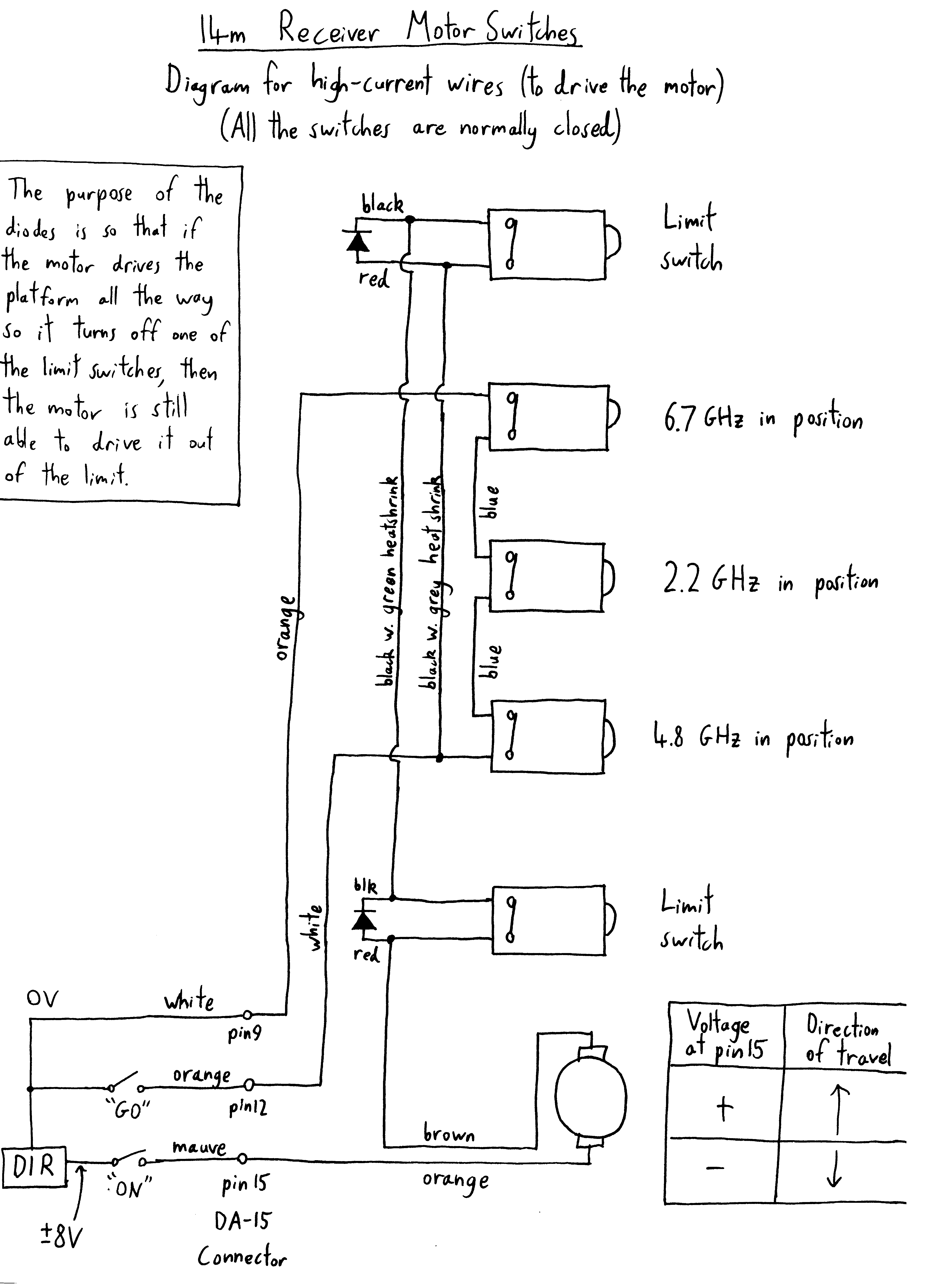
Wiring of platform motor and switches.
The switches do 2 things:
- Actually cut the power to the motor, so the platform stops. Uses the normally-closed side of each switch.
- Have a switch going to the the PIC, so it knows where the platform is. (normally open.)
When the platform drives into one of the switches, power will be immediately cut to the motor.
The PIC is able to turn on a relay ('GO') which overrides these switches.
The limit switches are not overridable, instead they are wired in parallel with a diode, which allows the platform to get out of the limit.
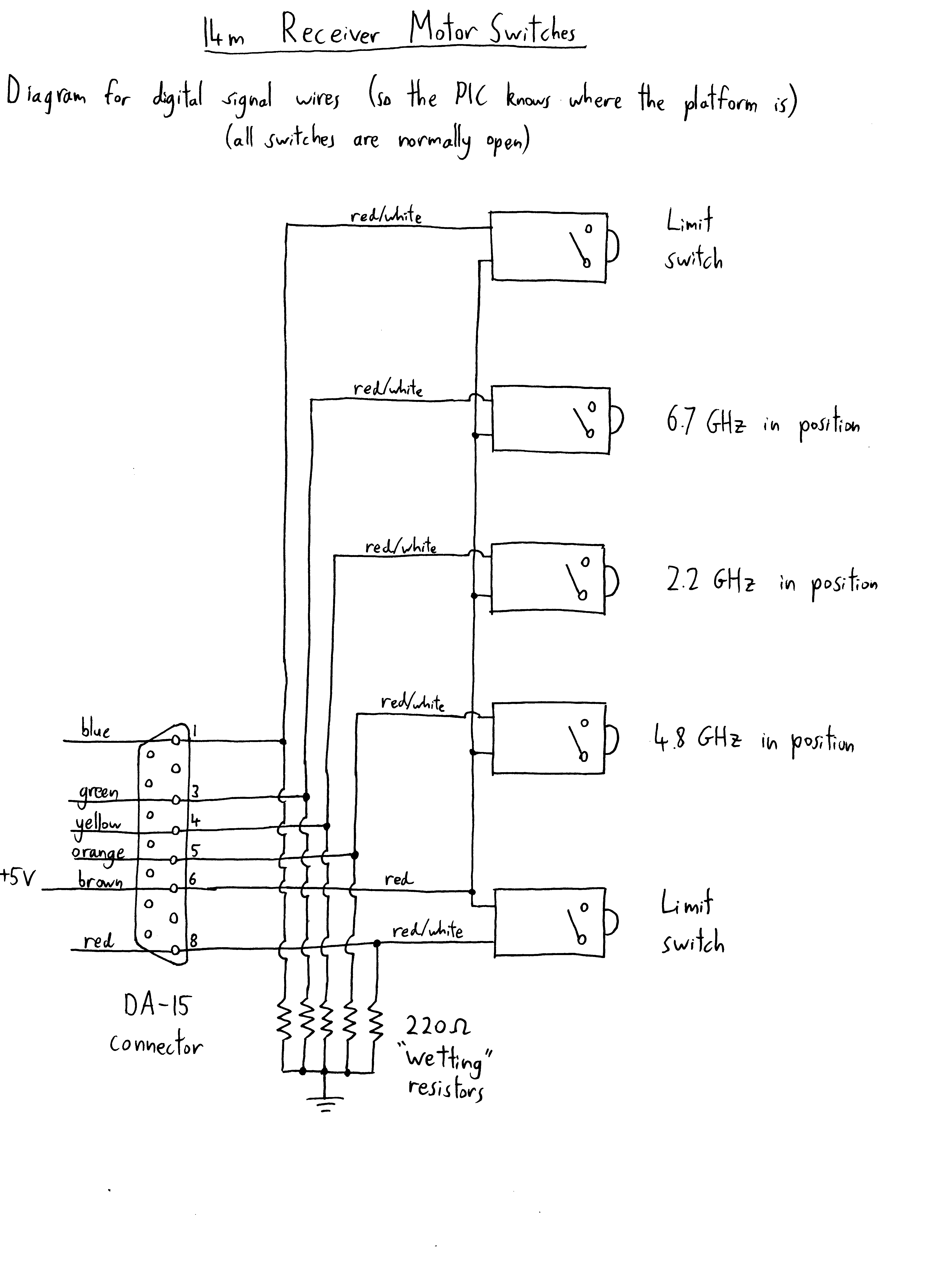
Wiring of digital side of switches.
On the digital side of the switches, there is a 220 Ohm pull-down resistor connected to each switch.
Without these, there would only be a 10 kOhm pulldown (located on the PIC board).
The purpose of these is to allow some wetting current to flow when the switch is on.
Without these, the switches were unreliable.